Class-A compliance for the most demanding power quality tests
The Fluke 1760 Three-Phase Power Quality Recorder is fully compliant to IEC 61000-4-30 Class-A, for advanced power quality analysis and consistent compliance testing. Designed for analysis of utility and industrial power distribution systems, in medium- and low-voltage networks, this power quality monitor provides the flexibility to customize thresholds, algorithms, and measurement selections. The 1760 power recorder captures the most comprehensive details on user-selected parameters.
Applications
Detailed disturbance analysis – Perform high-speed transient analysis and uncover root cause of equipment malfunction for later mitigation and predictive maintenance. The fast transient option, with its 6000 V measurement range, allows capture of very short impulses such as lightning strikes.
Class-A quality-of-service compliance – Validate incoming power quality at the service entrance. Thanks to Class A compliance, the Fluke 1760 allows undisputable verification.
Event correlation at multiple locations – Utilizing GPS time synchronization, users can quickly detect where a fault occurred first, either inside or outside the facility.
Galvanic separation and DC coupling – Allows complete measurements on dissimilar power systems. For example troubleshoot UPS systems by simultaneously recording the battery voltage and power output.
Power quality and power load studies – Assess baseline power quality to validate compatibility with critical systems before installation and verify electrical system capacity before adding loads.
- Fully Class-A compliant: Conduct tests according to the stringent international IEC 61000-4-30 Class-A standard
- GPS time synchronization: Correlate data with events or datasets from other instruments with precision
- Flexible and fully configurable thresholds and scale factors:Allows user to pinpoint specific issues by defining the detailed criteria for detection and recording of disturbances.
- Uninterrupted power supply (40 minutes): Never miss important events – even record the beginning and end of interruptions and outages to help determine the cause
- 10 MHz, 6000 Vpk waveform capture: Get a detailed picture of even the shortest event
- 2 GB data memory: Enables detailed, simultaneous recording of numerous power parameters for long periods of time
- Comprehensive software included: Provides trend diagrams for root cause analysis, statistical summaries, report writing and real-time data monitoring in the online mode
- Plug and play: Allows quick setup with automatic sensor detection; sensors are instrument powered, eliminating the need for batteries
- Rugged field design: Insulated housing and a solid state design with no rotating components enable reliable testing under nearly any conditions
| Product Feature | Fluke 1760 Basic | Fluke 1760TR Basic | Fluke 1760 | Fluke 1760TR |
| Power quality statistics according to EN50160 | ● | ● | ● | ● |
| Voltage event list (dips, swells and interruptions) | ● | ● | ● | ● |
| Continuous recording of: |
| Voltage | ● | ● | ● | ● |
| Current | ● | ● | ● | ● |
| Power P, Q, S | ● | ● | ● | ● |
| Power factor | ● | ● | ● | ● |
| kWh | ● | ● | ● | ● |
| Flicker | ● | ● | ● | ● |
| Unbalance | ● | ● | ● | ● |
| Frequency | ● | ● | ● | ● |
| Voltage and current harmonics to the 50th / Interharmonics | ● | ● | ● | ● |
| THD | ● | ● | ● | ● |
| Mains signaling | ● | ● | ● | ● |
| Triggered recordings | ● | ● | ● | ● |
| Online mode (Oscilloscope, transients and events) | ● | ● | ● | ● |
| Fast transient analysis up to 10 MHz | | ● | | ● |
| 4, 600V voltage probes | | | ● | ● |
| 4 dual-range flexible current probes (1000 A / 200 A ac) | | | ● | ● |
| GPS time sync receiver | | | ● | ● |
| Memory | 2 GB Flash memory |
| Overview of Measurement Functions |
| Statistical Evaluation | | Power quality statistics according to EN50160 and DISDIP tables like ITIC, CEBEMA, ANSI |
|
| Event List | | Dips, swells and interruptions are detected and stored in the event list. Also any trigger which fires generates an event added to this list. | | The Event list shows the exact time when the event occurred as well as the duration and magnitude. Sorting by several attributes of these events is possible to select one for further root cause analysis. | | RMS values, transients and fast transients can be stored if a trigger fires. |
|
| Continuous Recording | | Fluke 1760 records rms values together with corresponding minimum and maximum values for: | | • Voltage | | • Current | | • Power P, Q, S | | • Power Factor | | • kWh | | • Flicker | | • Unbalance | | • Frequency | | • Harmonics/Interharmonics | | continuously with the following time aggregations: | | Day | | 10 min | | Free Interval, e.g.: 15 min, 2h |
|
| Triggered Recordings | | rms: | Aggregation time is adjustable between 10 ms (1/2 cycle), 20ms (1 cycle), 200ms (10/12 cycles) or 3 sec (150/180 cycles). | | Calculating rms values, Harmonics and Interharmonics is performed synchronous to the power frequency. | | Basic aggregation for harmonics and interharmonics is 200ms | | Oscilloscope: | Sample rate is 10.24 kHz for all 8 channels | | Fast Transients: | Sample rate is selectable from 100 kHz to 10 MHz for channel 1-4 FFT of Fast Transients |
|
| Mains Signalling | | Phases and N-conductor, Voltage and current |
|
| Online Mode | | Variable refresh rate. This feature allows verification of instrument set up and delivers a quick overview of oscilloscope, transients and events. |
|
| General Data |
| Intrinsic uncertainty | | refers to reference conditions and is guaranteed for two years |
|
| Quality system | | developed, manufactured as per ISO 9001: 2000 |
|
| Environment conditions | | Operating temp. range: | 0 °C to +50 °C; 32 °F to +122 °F | | Working temp. range: | -20 °C to +50 °C; -4 °F to +122 °F | | Storage temp. range: | 20 °C to +60 °C; -4 °F to 140 °F | | Reference temperature: | 23 °C ± 2 K; 74 °F ± 2 K | | Climatic class: | B2 (IEC 654-1), -20 °C to +50 °C; -4 °F to +122 °F | | Max. operating altitude: | 2000 m: max. 600 V CAT IV*, power supply: 300 V CAT III 5000 m: max 600 V CAT III*, power supply: 300 V CAT II
* depending on sensor |
|
| Reference conditions | | Environment temp.: | 23 °C ± 2 K ; 74°F ± 2 K | | Power supply: | 230 V ± 10 % | | Power frequency: | 50 Hz / 60 Hz | | Signal: | declared input voltage Udin | | Averaging: | 10 minute intervals |
|
| Housing | | insulated, robust plastics housing |
|
| EMC | | Emission: | Class-A as per IEC/EN 61326-1 | | Immunity: | IEC/EN 61326-1 |
|
| Power supply | | Range: | AC: 83 V to 264 V, 45 to 65 Hz | | DC: 100 V to 375 V | | Safety: | IEC/EN 61010-1 2nd edition | | 300 V CAT III | | Power consumption: | max. 54VA | | Battery pack: | NIMH, 7.2 V, 2.7 Ah | | In case of a power supply failure an internal battery maintains the supply for up to 40 minutes. Afterwards, or in case of discharged accumulators the Fluke 1760 is turned off and continues the measurements with the latest settings as soon as the supply voltage returns. The battery can be replaced by the user. |
|
| Display | | Fluke 1760 features LED indicators for the status of the 8 channels, phase sequence, power supply (mains or accumulator), memory usage, time synchronization, and data transfer. | | Power LED: | • Permanent light: normal power supply from mains. | | • OFF: supply via internal accumulator in case of a power failure. | | Channel LEDs | 3-color LEDs per channel for: | | • overload condition | | • under load condition | | signal level in nominal range |
|
| Data memory | | 2 GB Flash memory depending on model |
|
| Memory model | |
| Interfaces | | Ethernet (100MB/s), compatible to Windows® 98/ME/NT/2000/XP RS 232, external modem via RS 232 |
|
| Baud rate for RS 232 | |
| Dimensions | | 325 mm x 300 m x 65 mm; 2.8 x 11.8 x 2.6 in. (H x W x D) |
|
| Weight | | appr. 4.9 kg; 10.8 lbs. (without accessories) |
|
| Warranty | |
| Calibration interval | | 1 year recommended for Class-A, otherwise 2 years |
|
| Signal Conditioning |
| Range for 50 Hz systems | | 50 Hz ± 15 % (42.5 Hz to 57.5 Hz) |
|
| Range for 60 Hz systems | | 60 Hz ± 15 % (51 Hz to 69 Hz) |
|
| Resolution | |
| Sampling frequency for 50 Hz power frequency | | 10.24 kHz, The sampling rate is synchronized to mains frequency. |
|
| Uncertainty for frequency measurements | |
| Uncertainty of internal clock | |
| Measurement intervals | | Aggregation of the interval values as per IEC 61000-4-30 Class-A | | Min-, Max-values: | Half cycle, e.g.: 10 ms rms values at 50Hz | | Transients: | Sample rate 100 kHz to 10 MHz per channel |
|
| Harmonics | | as per IEC 61000-4-7:2002: 200 ms |
|
| Flicker | | as per EN 61000-4-15:2003: 10 min (Pst), 2 h (Plt) |
|
| Measurement Inputs |
| Number of inputs | | 8 galvanically isolated inputs for voltage and current measurements. |
|
| Sensor safety | | up to 600 V CAT IV depending on sensor |
|
| Basic safety | |
| Nominal voltage (rms) | |
| Range (peak value) | |
| Overload capacity (rms) | |
| Voltage rise rate | |
| Input resistance | |
| Input capacitance | |
| Input filter | | Each channel is equipped with a passive low-pass filter, an anti-aliasing filter and a 16-bit A/D converter. All channels are sampled synchronously with a common quartz-controlled clock pulse. | | The filters protect against voltage transients and limit the signal rise rate, reduce high frequency components and especially the noise voltage above half the sampling rate of the A/D converter by 80 dB, thus achieving very small measuring errors in an exceptionally large amplitude range. This is also valid under extreme operating conditions like transient voltages at the output of converters. |
|
| Uncertainties |
| Uncertainty at reference conditions | | Uncertainty including the voltage sensors is in compliance with IEC 61000-4-30 Class-A. All voltage sensors are suitable for DC up to 5 kHz | | With Sensor 1000 V | 0,1% at Udin = 480 V and 600 V P-N | | Sensor 600 V | 0,1% at Udin = 230 V P-N |
|
| Intrinsic uncertainty for harmonics | | Class I as per EN 61000-4-7:2002 |
|
| Reference conditions | | 23 °C ± 2 K < 60 % rH; 74 °F ± 2 K < 60 % rH | | Warmed up instrument > 3h | | Power supply: 100 V to 250 V ac |
|
| Temperature drift | |
| Aging | |
| Common mode rejection | |
| Temperature drift | | Change of amplification through temperature: < 0.005 %/K |
|
| Aging | | Change of amplification due to ageing: < 0.04 %/year |
|
| Noise | | Noise voltage, input short-circuited: < 40 µV |
|
| DC | | ± (0.2% rdg + 0.1% sensor) |
|
| Technical Specifications |
| Power quality measurement standards | | Conformance | IEC 61999-1-4 Class 1, IEC 61000-4-30 Class A or B depending on measurement function, IEEE519, IEEE1159, IEEE1459 and EN50160 | | Clock/calendar | Leap years, 2 4-hour clock | | Real-time clock accuracy | Not more than ± 1 s/day | | Internal memory capacity for data | At least 2 GB | | Maximum recording period | At least 31 days | | Measurement time control | Automatic | | Maximum number of events | Limited only by the size of the internal memory | | Power requirements | 100 to 2 40 V rms ± 10 %, 47-63 Hz, 40 W | | Operating time during interruptions (internal UPS operation) | 5 minutes per interruption, 60 minutes total operating time without recharging | | Dimensions | 215 mm x 310 mm x 35 mm (8.5 in x 12.2 in x 3.5 in) | | Mass (weight) | 6.3 kg (14 lb) |
|
| Input | | Measurement types | One Phase Plus Neutral, One Phase IT No Neutral, One Phase Split Phase, Three Phase Wye, Three Phase Delta, Three Phase IT, Three Phase High Leg, Three Phase Open Leg, 2 Element Delta, 21/2 Element Wye | | Input channels | Voltage: 4 channels, ac/dc | | Current: 5 channels | | Voltage channels | Input resistance: 2 MΩ | | Input capacitance: < 2 0 pF | | Current input characteristics | 2 V rms = full scale, 1 MΩ Input Impedance for ferro CTs, low impedance for Flexi-CTs | | Measuring method | Simultaneous digital sampling of voltage and current. Digital PLL synchronized sampling, internal frequency reference used during voltage drops. |
|
| Synchronization and sampling | | PLL-synchronization source | The PLL synchronizes to the A-N voltage for wye power types, and to the A-B voltage for delta power types. All listed power types can be characterized as either wye or delta. | | PLL lock range | 42.5 to 69 Hz | | Sampling frequency | Voltage and current: 2 56 samples/cycle Inter-harmonics per IEC 61000-4-7: 2 560 points/10 cycles (50 Hz), 3072 points/12 cycles (60 Hz) Transient Voltage: 5 MHz | | A/D resolution | Voltage and current: 2 4 bits | | Transient voltage: 14 bits |
|
| Voltage and current measurements | | Voltage measurement range | AC voltage: 1000 V rms ± 10 % over range | | DC voltage: ± 1000 V + 10 % over range | | Voltage crest factor | 3 or less | | Current measurement range | Depends on current probe used | | Current crest factor | 4 or less |
|
| RMS voltage | | Measurement type | True rms calculated continuously: every cycle, every 1/2 cycle, and every 10 or 12 cycles at 50 or 60 Hz respectively, as required by IEC 61000-4-30. | | Measurement uncertainty | AC: ± 0.2 % reading ± 0.1 % full scale, above 50 V rms | | DC: ± 0.5 % reading ± 0.2 % full scale, above 50 V dc |
|
| RMS current | | Measurement type | True rms calculated continuously: every cycle, every 1/2 cycle, and every 10 or 12 cycles at 50 or 60 Hz respectively, as required by standards |
|
| Transient voltage (impulse) | | Measurement type | Waveshape sampling | | Full scale | 8000 V pk | | Sample resolution | 200 nS | | Measurement uncertainty | ± 5 % reading ± 2 0 V (test parameters: 1000 V dc, 1000 V rms, 100 kHz) |
|
| Voltage swell (rms swell) | | Measurement type | True rms (one cycle calculation by overlapping each half cycle – voltage between lines is measured for 3P3W lines and phase voltage is measured for 3P4W lines) | | Displayed data | Amplitude and duration of swell | | Measurement | Same as rms voltage |
|
| Voltage dip (rms sag) | | Measurement type | True rms (one cycle calculation by overlapping each half cycle – voltage between lines is measured for 3P3W lines and phase voltage is measured for 3P4W lines) | | Displayed data | Amplitude and duration of dip or interruption | | Measurement | Same as rms voltage |
|
| Voltage dropout (interruption) | | Measurement type | Same as voltage dip |
|
| LAN interface | | Connector | RJ-45 | | Speed and type | 10/100 Base-T, auto MDIX | | Communications protocol | TCP/IP over Ethernet |
|
| Wireless controller interface | | Connection | wireless (2.4 GHz radio) | | Speed | up to 700 kbit/second | | Communications protocol | Bluetooth SPP |
|
| Power Measurements |
| Power, battery life | | Measurement type | True rms calculated continuously: every cycle, and every 10 or 12 cycles at 50 or 60 Hz respectively, as required by standards |
|
| Frequency | | Measurement range | 42.5 to 69 Hz | | Measurement source | Same as PLL synchronization source | | Measurement accuracy | ± 10 mHz (10 to 110 % of range, with sine wave) |
|
| Power Factor | | Measurement range | 0.000 to 1.000 | | Measurement accuracy | ± 1 digit from the calculation of each measured value (±3 digits for total) |
|
| Displacement power factor | | Measurement method | Calculated from the phase difference between voltage fundamental and current fundamental | | Measurement range | – 1.000 (leading) to + 1.000 (lagging) | | Measurement accuracy | ± 0.5 % reading ± 2 % full scale ± 1 digit |
|
| Voltage unbalance and phase sequence | | Measurement method | Positive sequence voltage divided by negative sequence voltage, per IEC 61000-4-30 |
|
| Harmonic voltage and current | | Analysis window | rectangular | | Analysis order | 1st to 50th order | | Measurement accuracy | Voltage / Current: 1st to 2 0th orders: ± 0.5 % reading ± 0.2 % full scale, 2 1st to 50th orders: ± 1 % reading ± 0.3 % full scale (current sensor accuracy must be included for current and power) | | Measurement method | IEC 61000-4-7 |
|
| Inter-harmonic voltage and current (intermediate harmonics) | | Analysis window | rectangular | | Analysis orders | 1.5 to 49.5th order | | Measurement method | IEC 61000-4-7 |
|
| Flicker | | Measurement method | IEC 61000-4-15 | | Plt for 2 hours and PSt for 10 minutes | | Measuring range: | 0,1 to 5 (25) depending on voltage level, modulation and frequency |
|
| Environmental Specifications |
| Environmental | | Operating environment | Indoors or in covered area outdoors, up to 2 000 m altitude | | Storage temperature and humidity | -20 °C to 50 °C, 80 % RH max, non-condensing | | Operating temperature and humidity | 0 °C to 40 °C, 80 % RH max, non-condensing |
|
| Maximum rated working voltage | | Voltage terminals | 1100 V rms | | Voltage durability | 5550 V rms ac for 1 minute, between voltage input terminals, voltage input terminals and current probes, and voltage input terminals and case (50/60 Hz, 1 mA sense current) | | Enclosure protection | IP30 (per EN 60529) |
|
| Standards: | | EMC | EN 61326-1:1997+A1:1998 Class A | | EN 61000-3-2:1995+A1:1998+A2:1998 | | EN 61000-3-3:1995 | | Safety | EN 61010-1 2 nd Edition; 2 000 | | Voltage input unit: Contamination Level 2 , Overvoltage Category 1000 V CAT III, 600 V CAT IV (anticipated overvoltage: 8000 V) |
|
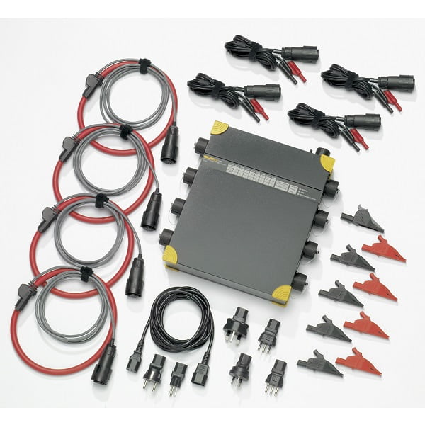
Power Logger Includes:
- Internal Flash-memory 2 GB
- PQ Analyze software on CD-ROM
- Ethernet cable for network connection (1)
- Crosslink Ethernet cable for direct PC connection (1)
- Mains cable (1)
- Operational manuals
- Carrying bag
- Voltage probes, qty 4 (600 V for INTL set, 1000 V for US set)
- Current probes, qty 4 (Dual-range flexible current probes 1000 A / 200 A AC)
- GPS time sync receiver
- Free ACT calibration certificate
Click on the link below to download the data sheet:
1760 DATA SHEET


Reviews
There are no reviews yet.